-
Git hooks with pre-commit
I was listening to the episode Get inside the .git folder on the podcast Talk Python To Me and learned about pre-commit hooks. Git hooks are commonly used with linters and formatters.
In this post, we’ll create a hook with pre-commit that runs prior to committing using the formatter black and the linter flake8. The goal is to keep code up to standards and as readable as possible. But first:
What are hooks?
You can find the hooks folder within
repo/.git/hooksThis directory contains shell scripts that are invoked after the Git commands they are named after. For example, after you run a commit, Git will try to execute the post-commit script, if it has executable permissions.
Here’s a full list of hooks available:
- applypatch-msg
- pre-applypatch
- post-applypatch
- pre-commit
- prepare-commit-msg
- commit-msg
- post-commit
- pre-rebase
- post-checkout
- post-merge
- pre-receive
- update
- post-receive
- post-update
- pre-auto-gc
- post-rewrite
- pre-push
How to create a hook without pre-commit
$ cd your_repo/
$ vim repo/.git/hooks/pre-commit
add the following:
#!/bin/bash
echo Luke makes the best pre-commit hooks
echo PWD is $PWD
Now each time you commit, this will run before the commit finishes.
pre-commit creates these scripts automatically
Pre-commit generates these scripts for you from a
.yamlfile then stores the generated script in the appropriate place withinrepo/.git/hooks/<hook_type>. Here’s an example of the script that is generated by pre-commit after following the instructions below.How to configure pre-commit with black and flake8
$ cd your_repo/
$ python3 -m venv env
$ source env/bin/activate
$ pip install pre-commit
optional:
$ pip freeze > requirements.txtto update your requirementsCreate the pre-commit
.yamlfile in your repository$ vim .pre-commit-config.yamlrepos: - repo: https://github.com/psf/black rev: 20.8b1 # Replace by any tag/version: https://github.com/psf/black/tags hooks: - id: black language_version: python3 # Should be a command that runs python3.6+ - repo: https://github.com/pycqa/flake8 rev: 3.9.1 # Replace by any tag/version: https://github.com/PyCQA/flake8/tags hooks: - id: flake8Have pre-commit generate the script from your
.yamlfile and output it intorepo/.git/hooksthen format and lint all existing files in your repository$ pre-commit install $ pre-commit run -allFrom now on, when you commit, this hook will run then format and lint all your modified files in this repository.
see also
-
Avoiding compatibility issues when sharing sketches between ESP32 and ESP8266
I learned that you can use macros to automatically decide which library based on which device is being used. This lets you avoid a lot of work when switching between boards.
#ifdef ESP8266 #include <ESP8266WiFi.h> #else #include <WiFi.h> // for ESP32 #endif -
Hiding Sensitive Credentials on Platform IO Projects
I was wondering how to keep from removing and adding my wifi credentials and IP addresses in my arduino projects. Paul pointed me towards using a header file.
Using PlatformIO, create the file at
/project/include/secrets.h/and enter:#ifndef SECRETS #define SECRETS const char *ssid_name = "wifi network name"; const char *ssid_password = "wifi network password"; const char *rbp_ip = "ip address"; #endifI’m not sure if a header guard is necessary here, but it seems like good practice. Don’t forget to add
secrets.hto your.gitignore!Then make the changes in your
/project/src/main.cpp:#include <Adafruit_GFX.h> ... #include <PubSubClient.h> #include "secrets.h" // wifi credentials const char *ssid = ssid_name; const char *password = ssid_password; // MQTT WiFiClient espClient; PubSubClient client(espClient); const char *mqtt_server = rbp_ip; // IP to broker (raspberry pi) // screen pinout #define TFT_CS D0 #define TFT_RST D1 #define TFT_DC D2 ... -
Getting organized with Fritzing
ESP8266 oven thermometer schematics made by me Fritzing is a way to create schematics of circuitry. Before this I wasn’t using anything like it and relied mainly on pictures I had taken. Now that I’m using Fritzing and I feel significantly more organized. I think it makes it a lot easier to think about what I’m doing. An added bonus is it’s a lot easier to share with other people.
It comes with some components, but it’s not all of them. When you need more you just search for the part with google and make sure to include “.fzz”. I’ve found most parted I’ve needed exactly except for the cheap MAX6675 chip I purchased off of Amazon. For that one, I had to modify another part, the one that says “Mono 2.6W”. It has the right pin order and I was able to modify it using edit part.
An example of a project I’ve used this on can be found here.
-
Learning the importance of understanding pins on the ESP8266
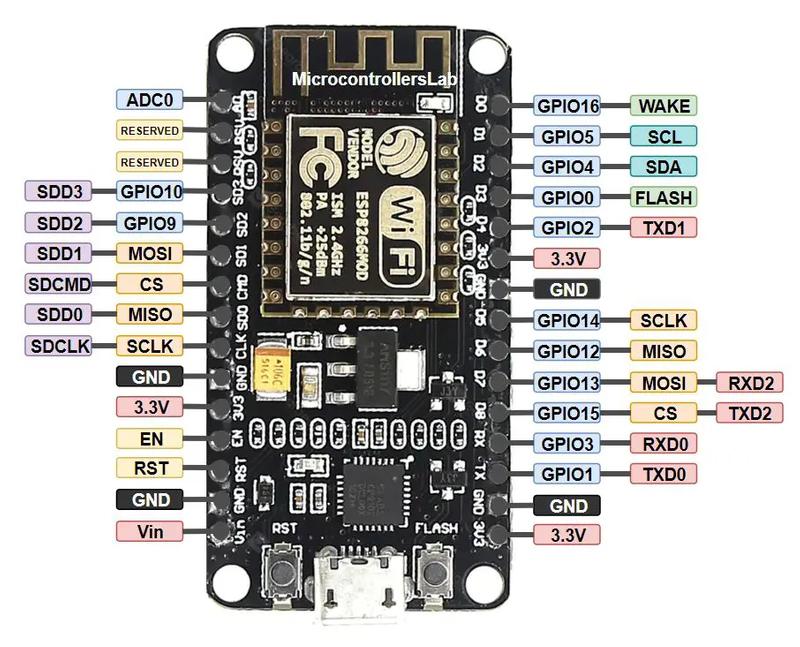
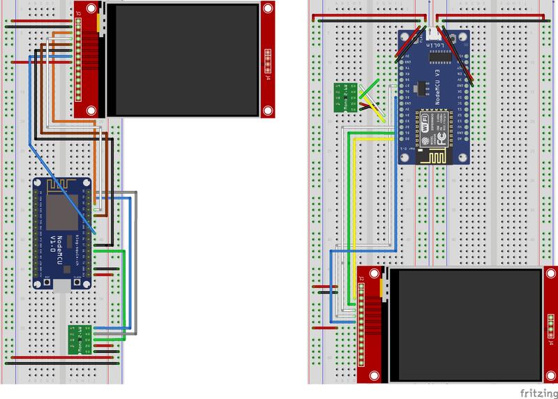
ESP8266 pinout diagram (source) While working on my oven thermometer project, I realized that I was going to need more space for more modules and enabling the touchscreen. I also decided to take advantage of the power rails on the side of the breadboards.
I figured out how to use Fritzing, got some custom components for a real representation of my board, and put together the schematic for the single breadboard. After feeling like I had that put together and Fritzing figured out for the most part, I started to plan out my two breadboard configuration.
When I put together the single board, I followed tutorials, but this time I decided to just move it all myself. I also noticed that my pins were a mess. Parts of the temperature sensor were plugged into D0, D1, then D8. The screen was plugged in at seemingly random spots. D3 was unused. I thought it’d be nice if they all were placed sequentially (D0, D1, D2…). I knew what I was doing. I thought…
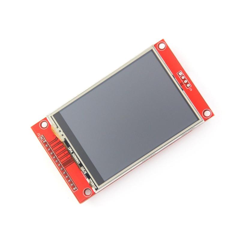
ILI9341 TFT LCD (source) My first mistake was thinking the ILI9341 only needed to connect to VCC, GND, CS, RESET, OC, and LED. But it turned out that SCK (serial clock) and MOSI (master out slave in) were necessary to get the screen to show more than just the backlight. After riding the struggle bus for a while, I finally went back to a tutorial and fixed the issue. Won’t forget that.
My second mistake was, once again, not fully understanding the pins. Turns out, D3 isn’t just a GPIO pin, but it’s also the “Flash” pin. When I’d go to flash the ESP8266 from my computer with my new configuration (now using D3), my computer couldn’t detect the ESP. It wouldn’t show up in LSUSB at all. I noticed however, that when I took the ESP all the way off the board, I was able to flash it. Now I’ve gotta make sure to always unplug D3 before I go to flash.
I’m currently only using the right side of the ESP. I need to figure out what all the left side is capable of…